
|
| The Cable Railway Company published "Cable Railway Company's System of Traction Rail Ways for Cities and Towns" in 1881 to promote its wares. Read more about The Cable Railway Company. Thank you to Google Books. |
From Cable Railway Company's System of Traction Railways
for Cities and Towns
CABLE RAILWAY COMPANY
INCORPORATED UNDER THE LAWS OF THE STATE OF CALIFORNIA,
APRIL 16TH, 1881.
CAPITAL. . . . $1,000,000.
| President, | . . . | A. S. HALLIDIE, |
| Vice President, | . . . | ROBERT F MORROW, |
| Treasurer, | . . . | F F. LOW, |
| Secretary, | . . . | C. P. CAMPBELL |
DIRECTORS.
| JOSEPH BRITTON, | F. F. LOW, |
| H. L. DAVIS, | JAMES MOFFITT, |
| A. S. HALLIDIE, | ROBERT F MORROW, |
| J. L. SCHMITT. | |
Counsellors at Law, Messrs. Estee & Boalt, San Francisco.
Office of the Company, No. 6 California Street, SAN FRANCISCO, CALIFORNIA,
NOTICE
The Cable Railway Company was organized for the purpose of introducing throughout the United States the system of Cable Railways, matured by Mr. A. S. Hallidie, and as operated in the city of San Francisco.
This Company is the successor of A. S. Hallidie, the Traction Railway Company, and the Hovey Patent Rights Company, in whom were vested the various patents covering this system of street Railway. The various interests have been consolidated with the intention of providing for the proper introduction and practical working of this system, and for the protection of the public and of those interested.
The Cable Railway Company is the exclusive owner of the following United States Letters Patent, to wit:
| No. 100,140 | Feb. 22, 1870. | No. 183,928 | Oct. 31, 1876. |
| 127,690 | June 11, 1872. | 183,929 | Oct. 31, 1876. |
| 163,865 | June l, 1875. | 184,624 | Nov. 21, 1876. |
| 176,136 | April 18, 1876. | 195,372 | Sept. 18, 1877. |
| 179,016 | June 20, 1876 | 195,504 | Sept. 25, 1877. |
| 179,786 | July 11, 1876 | 195,505 | Sept. 25, 1877. |
| 181,817 | Sept. 5, 1876 | Reissue No. 7339 | Oct. 10, 1876. |
| 182,663 | Sept. 26, 1876 | Reissue No. 7607 | April 17, 1877. |
The foregoing include all the original patents granted to Mr. A. S. Hallidie.
Under the patents above mentioned, the following Street Railroads have been constructed and are now operating under licenses granted to them, viz:
| Clay Street Hill Railroad Company | San Francisco. |
| Sutter Street Railroad Company | San Francisco. |
| California Street Railroad Company | San Francisco. |
| Geary Street Railroad Company | San Francisco. |
| Presidio and Ferries Railroad Company | San Francisco. |
| Chicago City Railway Company | Chicago. |
The Cable Railway Company, having sustained the validity of its patents in the United States Circuit Court for the District of California, is prepared to GRANT LICENSES, and furnish all information, drawings, etc., together with competent constructing Engineers if desired, to Street Railway Companies proposing to build.
The unauthorised construction of Street Railroads, worked by a moving endless cable, in an underground tube, on the principle of the Cable Railroads now operating in San Francisco, will be an infringement upon the patent rights owned by the Cable Railway Company, and any infringement of the patents for construction, as well as those pertaining to the operating of such roads, will be prosecuted to the full extent of the law.
Address
CABLE RAILWAY COMPANY,
P. O. BOX 2080.
No. 6 California Street,
SAN FRANCISCO, CAL,
THE CABLE RAILWAY COMPANY'S
SYSTEM OF
STREET RAILWAY.
AS OPERATED IN
SAN FRANCISCO, CALIFORNIA, AND CHICAGO, ILLINOIS.
This system of Street Railroad, the invention of Mr. A. S. Hallidie, was first put in use by the Clay Street Hill Railroad Company, in the City of San Francisco, California, August, 1873, since which time it has been constantly running, and has been found to answer all requirements, and to exceed the expectation of engineers and others who had examined the plans of the inventor.
It is adapted to all kinds of metropolitan railroading, where the surface of the streets has to be kept free from obstructions and open to ordinary traffic, where locomotive steam engines are not permitted, or where the streets are so steep as to make the use of horses difficult or impossible.
The system consists of an endless wire rope placed in a tube below the surface of the ground, between the tracks of a railroad, and kept in position by means of sheaves, upon and beneath which the rope is kept in motion by a stationary engine, the power being transmitted from the motor to the rope by means of grip or other suitable pulleys, and from the rope to the cars on the street by means of a gripping attachment fixed to a grip-car or dummy, and connected by a thin bar, which passes through a narrow slot in the upper side of the tube.
It presents no impediment to ordinary travel. The rope is grasped and released at pleasure by a gripping device attached to the passenger car, and controlled by a man in charge. The car is more smoothly started than by horses, and instantly stopped on any part of the road; its mechanical construction is simple and easily controlled, and on the streets of a city it does not frighten horses or endanger lives.
A description of this system, as in use by the Clay Street Hill Railroad Company of San Francisco, will best explain the modus operandi.
Clay street is a central street in the City of San Francisco, and for a number of blocks near the lower terminus of the road is very densely populated. The street is only 49 feet wide from house to house, and between the sidewalks is occupied by two lines of gas pipe, one line of water pipe, a street sewer, and at the cross streets by water cisterns.
The lower terminus of the road is at the intersection of Kearny and Clay streets. The summit of the hill is 807 feet above Kearny street. The incline on Clay street has a double track, and is 5,197 feet long; the rope runs into the engine house at Leavenworth street. The ascending grades are as follows (see profile of street grades, Fig. 7): From Kearny to Dupont, 45 feet; from Dupont to Stockton, 45 feet; from Stockton to Powell, 62 feet; from Powell to Mason, 42 feet; from Mason to Taylor, 48 feet; from Taylor to Jones, 67 feet. Then the grade descends, as follows: Jones to Leavenworth, 15 feet; Leavenworth to Hyde, 50 feet: Hyde to Larkin, 50 feet; Larkin to Polk, 45 feet; and then an ascent of 15 feet from Polk street to Van Ness avenue. The distance between each street is 412 1/2 feet. Clay street runs at right angles to the above streets, which have widths varying from 45 feet to 68 feet 9 inches. All the street crossings are level. The steepest grade is 1 in 6 15/100.
The general arrangement of the system in use by the Clay Street Hill Railroad is as follows: An endless steel-wire rope, three inches in circumference, 11,000 feet long, is stretched the whole distance, lying in iron tubes, supported every 39 feet on 11-inch sheaves. This rope is supported at every change of angle at the lower crossings on sheaves four feet in diameter, passing around a horizontal sheave eight feet in diameter at the lower end of the line, and at the engine house around two angle sheaves, each eight feet in diameter, which lead the rope on the grip pulleys, also eight feet in diameter, which are driven by one 14 x 28 engine. The steam is furnished by one boiler, 16 feet x 54 inches, using 3,700 pounds of coal per day. They have also duplicate engine and boiler, which are held in reserve.
The grip pulleys being furnished at their circumference with jaws that grip and release the rope automatically, by the pressure of the rope in the jaws, prevents the rope from slipping; and, being set in motion by the engine, actuates the endless rope, while traveling up one tube and down the other.
In addition to the sheaves that support the rope in the tubes, at the upper side of each crossing where the incline makes an angle upwards, there are sheaves in the tubes that keep the rope down and from striking the upper part of the tube.
There is an opening in the upper side of the tube. This opening runs the entire length of each tube, forming a long slot three-fourths of an inch wide. This slot is not immediately over the center of the tube, but on one side, to keep sand and drift from falling on the rope, and enable the foot of the gripping attachment to pass by and under the upper sheaves, and over the lower sheaves in the tube.
The connection between the cars on the street and the traveling rope is made by means of this gripping attachment, which is hereinafter described. The cars are made to seat 14 passengers and the dummy 16, but not seldom as many as 44 have ridden in the car and 26 on the dummy -- 70 in all; and the roads with broad- gauge larger cars and more even grades have, in one load on car and dummy, carried as many as 160 passengers. It is true they were crowded, but this is always the case on holidays. The grip-car, or "dummy," with the gripping attachment, is attached to the passenger car firmly, so that there can be no danger of accident. The passenger car is amply provided with brakes. In addition to the usual car-brake, there is another attachment, operated from the platform in the same manner as ordinary brakes, which forces a broad band of wood down on each track immediately under the car. This arrangement is shown in Fig. 1. Strong iron drags are provided, so that if an accident should occur in going up the hill, they will immediately catch in the street, and prevent the car from going backwards. When it is necessary to back down hill, these drags are raised up out of the way by the conductor.
The "dummy" is also provided with powerful brakes. The "dummy" and car are connected with a suitable coupling, so that the weight of the car going down comes on the rope, and is utilized to draw up the other cars on the other track. The brakes are not usually employed when coming down, except when it is necessary to stop, as the car runs down with the same speed as the rope, as long as the gripping attachment is in connection with the rope.
By referring to the engravings, the system will be more clearly understood. Fig. 1 is a side view of road and car and dummy; the tube is in longitudinal section, and shows the arrangement of the rope; the upper pulleys for keeping the rope down where the grade changes upwards, and the lower or supporting pulley, also the gripping device attached to the dummy and to the rope.
Fig. 2 is a transverse section through the dummy and road-bed; the tube, supporting pulley, rope, and gripping device are shown, and the general mode of construction of the same.
Fig. 3 is an isometrical view of the road-bed -- a portion of the tube being removed to show the gripping device attached to the rope; the lower end of the shank is only shown (it is broken off in the drawing), being sufficient for the purpose; the construction of the tube and the tube frames is clearly shown, and the appearance of the rails and slot and surface of the street when paved.
Figures 4 and 5 show the gripping attachment used by the Clay Street Railroad Company in two different positions. A vertical slide works in a standard, and is moved up and down by a screw and hand-wheel. This screw is shown on the cut of dummy, Fig. 2. The small upper screw going down through the large screw operates it. At the lower end of this slide is a wedge-shaped block. The wedge actuates two jaws horizontally, which open and close according to the direction in which the slide is moved, closing when the slide is moved upwards. These jaws have pieces of soft cast-iron placed in them, which are easily removed when worn out. These pieces of iron are of proper shape and size inside to grip the rope when they are closed over it.
On both sides of these jaws, and attached to them, are two small sheaves. These sheaves are held by means of rubber cushions, sufficiently in advance of the jaws to keep the rope off from the jaws, and at the same time to lead the rope fairly between them, allowing it to travel freely between the jaws, when they are separated, without touching them. When it is required to grip the rope, this slide is drawn up by means of the small screw before described, and the wedge at the lower end closes the jaws over the rope, at the same time forcing back the small guide sheaves on to the rubber springs. The standard containing the slide, etc., is enclosed and retained in an iron bracket, shown on the dummy (Fig. 2), and raised and lowered bodily through an opening in the tube from above the surface of the street to the rope in the tube by means of a screw and nut, with hand-wheel attached. The iron bracket is secured to a traction car, called a dummy, as shown in Figures 1 and 2. The dummy is coupled to the passenger cars at the bottom of the incline, and uncoupled at the top, and vice versa. Horses can then be coupled to the cars if desired. As before stated, the rope is constantly in motion, running between sheaves placed in the tube. The slot of the tube is on one side of a vertical line drawn through the center of the tube, and referring to Figs. 4 and 6, it will be seen that the foot of the gripping attachment projects on one side, giving it an L shape, enabling the jaws to pass under and over the rope sheaves in the tube. In order to stop the car, the jaws of the gripping attachment are opened slightly; when they release the rope, the guide sheaves take it, and the car stops.
The shank of the standard containing the slide, which works in the slot of the tube, is one-half of an inch thick and 7 1/2 inches wide, there being one- eighth play on each side. All the essential parts of the gripping attachment are made of steel.
The rope runs 17 1/2 hours per day, at a speed of 6 miles per hour. The cars start every five minutes, except in the afternoon, when they start every three minutes.
The road has a gauge of 3 feet 6 inches. An ordinary 30-pound steel T rail is used on Clay street, which is set flush with the street, and presents a neat, smooth appearance. The stretching arrangement at the lower end keeps a constant strain on the rope under all circumstances.
This machinery is so arranged that the wire rope passes for some distance in open view of the engineer, so that it can readily be examined at any minute.
The hill is the best portion of the city for residences, and the road brings within five minutes of the business portion of the city a large amount of property that was comparatively worthless on account of the difficulty of access, but is now much sought after, having trebled in value since the road was completed.
After the Clay Street Hill Railroad had been running three years and a half, and the economy and practicability of the system was thoroughly tested, the SUTTER STREET RAILROAD COMPANY, whose lines had for many years been unprofitably worked by horses, changed their system from a horse road to the wire cable system; and by the end of the year 1879 had reconstructed nearly their entire road on this system. This Company has now 17,000 feet (over three miles] of double track operated on this system. The gauge of the road is 5 feet, and its greatest elevation is 167 feet above its initial point. (See profile of street grades, Fig. 10.)
The grades, however, are comparatively light, and it gave an opportunity to test the two systems, Horse v. Cable -- not, however, under circumstances very favorable to the cable, owing to the fact that the business of the road was not interrupted during the transformation, and the road was not reconstructed in a very substantial way. But, in spite of that, the saving in the running expenses of the road effected by the cable system was stated by the Superintendent and Secretary of this road, in the case of the Traction Railroad Company vs. Sutter Street Railroad Company for infringement of Mr. A. S. Hallidie's patents -- United States Circuit Court, California (decided against defendant) -- to be thirty per cent., and that the passenger traffic was increased 962,375 the first year after adopting the cable system. The shares of this Company were selling at $24 before the transfer, and are now selling at $60.
The cars of this Company seat 18 persons and the dummy 18. The gauge of the track is 5 feet, and the cable crosses two of the main thoroughfares of the city -- Kearny and Montgomery streets.
Their main cable line is on Sutter street, and is 13,291 feet long. A branch cable road runs at right angles to this on Larkin street, and is 3,712 feet long. This latter road runs across two other cable roads, viz: the California Street and Geary Street Railroad Company.
The gripping attachment used by this Company is somewhat different in construction from that on Clay street, although involving the same principles. The motion of the gripping jaws is vertical instead of horizontal, and it takes and releases the rope sideways, instead of beneath, as with Clay street; and in order to run on to or off from the rope at the termini of the cable road, the track and slot diverge from or converge to the line of the rope. Levers are used for operating the jaws instead of the screw.
The CALIFORNIA STREET RAILROAD commenced running April, 1878. length is 12,000 feet of double track, and it passed in that distance over two elevations, the heights being 265 feet and 235 feet above base respectively, the valley between being 125 feet above base. The gauge is 3 1/2 feet, same as the Clay Street.
This road, like Clay and Sutter Street, has been extended beyond the length of its original construction, which was 8,800 feet, and which was constructed in a very substantial manner, the tube being formed of worn out 65-pound rails, and surrounded by concrete.
The engine house is located in a valley about midway between the termini of the original section. Some of the grades on this line are quite heavy, there being a rise of 67 feet and 75 feet respectively in the distances of 412 1/2 feet. This is the heaviest grade in San Francisco, except one block on the line of the Presidio Railroad, which has a rise of 78 feet in the same distance. (See profile of grades, Fig. 8.)
This company uses a heavier rope than the other lines in this city, viz: 4- inch circumference, and the driving pulleys are on the same plane as the rope, and situated under the street.
The grip employed is worked by a lever, and, like Sutter Street, takes the rope sideways.
The GEARY STREET RAILROAD runs over a comparatively level street, and through the most central and populous streets of the city. It was completed and commenced running March, 1880.
The gauge of the road is 5 feet, and its length is 13,200 feet of double track, in which distance it passes over two elevations, 850 and 280 feet above base respectively, and attains a third elevation at its west terminus of 224 feet above base -- its starting point in the city being 35 feet above base, and the two intermediate valleys being 160 and 154 feet respectively.
The tube is constructed of cast-iron sections, and covered by concrete. The space inside the tube is much less than any of the other roads. The grip is worked by levers. It is vertical in its motion, and takes the rope from above, the gripping jaws being immediately under the slot, as is also the rope, which is thus exposed to the falling water, dirt, etc., which the other roads avoid by having the gripping jaws and rope sufficiently off on one side of the slot to escape falling particles.
The PRESIDIO AND FERRIES CABLE RAILROAD has a 5-foot gauge; 10,000 feet of double track. It ascends one hill 246 feet above its initial point in a distance of 5,000 feet. The engine is located on the summit of the hill, about midway between the termini, and about 700 feet from which is a very heavy grade of 78 feet in 412 1/2, or 1 in 5 3/10. The road is built very substantially, with cast- iron sections or yokes, connected by rolled channel iron and sheet iron.
The grip is the same as the one used on Clay street, although made heavier, to conform to the heavier grades and rolling stock.
There is a curve at the intersection of two streets, about 2,600 feet from the starting point, and the rope is deflected by means of two 8-feet diameter horizontal pulleys. The streets descend from both directions towards the curve, and about 80 feet before reaching the curve the grip is opened and released from the rope, the car and dummy are carried around by gravitation, and the rope is picked up again after passing the curve.
The ROSLYN TRAMWAY, in the city of Dunedin, New Zealand, is a Cable Railroad, 3' 6" gauge, single track, with turnouts. It is 3,500 feet long, and ascends 500 feet in that distance. It has two curves, both on grades.
This road has been operating about two years, under the patents granted to Mr. A. S. Hallidie in the colony of New Zealand.
The peculiar features of this road are:
1. Single track line, with two turnouts or sidings, both parts of the
rope running in opposite directions in one tube, except at the turnouts.
2. Two curves of 215 feet radius, forming a S.
3. Absence of level crossings, thus requiring stoppages to be made
on the grades.
At the curves, horizontal rope sheaves are placed in the tube, and the shank of the gripper is provided with a roller, which rests against a guard rail placed parallel to the track and slot inside the tube the length of the curve.
The engine is placed at the top of the hill.
The CHICAGO CITY RAILROAD COMPANY'S Cable Line, on State street, in the city of Chicago, is 4 7/10, miles long, with a double track, 5 foot gauge (Four foot, 8 1/2 inch -- JT), and runs on a very busy street, which is almost a dead level.
The climate of Chicago is one of extremes, the thermometer reaching 99 degrees in summer and zero-Fahrenheit in winter, and snow falls very heavily.
The tube in which the rope runs is made much deeper than in San Francisco, being over 4 feet in depth, and the rope is placed about 30 inches above the bottom of the tube, thus allowing for a certain accumulation of light snow which might drift in through the narrow slit in the top of the tube, but at the depth of 4 feet there is usually natural warmth enough to prevent any material freezing.
The foundation for the road-bed and tube was quite soft and yielding, and consequently needed a broad base of concrete to sustain the superstructure; hence the expense of construction was quite heavy.
The rope, which is 4 inches in circumference, is made of Swedish iron, and has 6 strands of 19 wires. All the driving and angle pulleys are 12 feet in diameter.
The engines at this time in use are two in number, of the "Wheelock" pattern; cylinder, 24" diameter by 20" stroke. Two other engines are ready for use as other Cable Lines in course of construction are completed. The boilers are in 4 sets of 2 each of what are known as the Babcock & Wilcox pattern.
The town end rope is run at 8 miles per hour; the suburban end at 10 miles. At the town terminus a second rope is employed, which is driven by a 6-foot pulley, placed on the same shaft as the 12-foot terminal pulley of the main cable, and consequently travels at one half the speed of the latter, and carries the dummy and cars around a square, making a return by way of Madison street, Wabash avenue, and Lake street to State street, passing around four corners.
The increase of passenger traffic has been so great that one dummy hauls two cars, carrying as high as 250 passengers in the train, and 35,000 passengers are carried daily.
Although this system was first adopted on roads where the grades are too steep for horses to work to advantage, the economy of its working has so demonstrated itself that all the level roads in San Francisco have obtained amended charters giving them the privilege of turning their horse roads into rope roads. The wear and tear on the streets, as well as the accumulation of filth due to horses, are entirely avoided. Humanity is not shocked by the overloading of street cars or the overworking of horses.
In cities where the severity of winter closes traffic for days at a time, this system can keep its own tracks clean by a cheap system of warming in the tube, or by having tubes of considerable depth, as employed in Chicago, and the great traction power of the rope on snow plows and scrapers -- a power which it is impossible for horses to produce struggling through the frozen and snow- covered tracks -- will enable the tracks to be kept clear.
The saving effected by the employment of this system is from thirty to fifty per cent, on that of horse roads, while its capacity for traffic is almost unlimited. The speed at which the cars travel is from 6 to 10 miles per hour.
The Cable Railway Company have acquired control of the various patents granted to Mr. A. S. Hallidie, the inventor of the system, and have also secured other patents relating thereto, and which control this system of street railroad. They therefore warn all persons or corporations against infringing on the same.
Companies or individuals desiring to negotiate for the use of the foregoing system, or construction of similar lines, can communicate with the
CABLE RAILWAY COMPANY,
OFFICE, No. 6 CALIFORNIA STHEET.
SAN FRANCISCO, CAL.
CABLE RAILROADS.
HISTORY OF THE GROWTH OF A CALIFORNIA INVENTION.
Description of the Wire Rope System for street Cars.
From the Mining and Scientific Press, of San Francisco
It is not very long since the mode of navigation through the streets of large cities was by means of sedan chairs, and to-day the jimrikisha (sic - JT) is the mode of locomotion through the principal cities of Japan. The street railway is a modern invention, and can be traced back to a very recent period; for, previous to 1850, street railways were not in use. It was about that date they were first introduced in the United States, and for many years they were enjoyed only in this country, but their success, pecuniarily or otherwise, soon caused their adoption in nearly all the leading cities of Europe.
Yet the idea was not new, for tramways were in use early in the seventeenth century; but the tramway of that date was a very different thing to the street railway, or tramway as it is called in Europe, of the present time. There is little new under the sun, and when the Romans paved the way for the wheels of their chariots to roll on, or smooth roads were made for people to tramp on, they were but the precursors of tramways, or trampways, and long before Mr. Outram, by a singularity of connection of name and subject, suggested the practical tramway of the pre-railway period.
Yet it is unfair to say that the street railway of to-day is an old idea revamped, because some one had an idea that something of the kind might be done in some kind of a way. Break the eggshell, and stand it on its end, and everybody will tell you they knew that before.
But long before street railways came into fashion, stage coaches lumbered along pretty fair roads for the time, and each took the ruts of its predecessors, and thus had a tramway of its own, with a hollow rail of Mother Earth to run on. But in those days everything ran or walked on the king's highway, and it was not then the trampway as it is to-day, when tramps rule the road.
But long before the street railway came into practical use, much had been done in the way of thinking about it, and various contrivances were invented, more or less impracticable, to facilitate the mode of passenger traffic in streets, and to render it easy, rapid, and cheap; but it was a long time before the old rumbling omnibus was supplanted by the horse cars of to-day, which have in their turn been, to a threatening extent, supplanted in New York City by the elevated railroads, and in San Francisco, 3,500 miles west, by the cable railroads.
It is the cable railroads, more particularly, that we are now interested in, and which threaten to revolutionize the street railroad system, and to abolish the horse cars; and to the history of this invention we now propose briefly to turn our attention, and look back a little to see what had been done in this particular previous to the conception of the first cable road in this city -- the Clay Street Hill Railroad -- by Mr. A. S. Hallidie.
Without wire ropes it would be difficult to work these cable roads economically and successfully. Wire rope was the invention of Mr. Andrew Smith, a native of Scotland, who experimented with the use of metal wire for ropes in 1828, and took out his first patent in Great Britain, January 12, 1835. Since then the material from which wire is made has been improved, until now steel wire is made capable of sustaining a tensile strain of 120 tons per square inch area.
Although the cable railroad was invented mainly to overcome the difficulties in ascending the heavy grades in this city, it has been found by experience that this system is equally applicable to level roads.
As a matter of interest in connection with this invention, it may be remembered that some years ago the cars of the Omnibus Railroad Company were hauled up Jackson street, from Kearny to Stockton, by extra horses, and that during the busy portion of the day three horses, driven tandem, were placed in front of the two horses attached to the car, and that the five had all they could do to haul the cars up two blocks -- the ascent being 73 feet in 875 feet.
It was while watching these cars being hauled up this street, and observing the painful difficulty the horses had in performing their work (two of the horses, having fallen, were dragged part way down hill), that Mr. Hallidie determined to find some more humane and effective way of performing that service.
He had been engaged in devising a way of conveying material over precipitous and mountainous roads by means of endless wire ropes elevated on posts above surface obstructions, snow, etc., and had successfully put in operation a method by which this was done when the descent was as great as 1 in 1 1/2. Those who were in San Francisco and attended the Mechanics' Fair of 1871 may remember seeing the wire tramway exhibited there by Mr. Hallidie -- a full-size line, with depressions, curves, and elevations, and carrying freight, passengers, and children -- to the delight of the latter. After perfecting this system, he devoted his attention to the solution of the problem he had in view, suggested to him by the incident above related.
At this time he was, and for two years previous had been. President of the Mechanics' Institute, which, together with other public duties, required much of his time and attention. Nevertheless, he applied himself to the subject of street railroads, and in 1871 he confidentially laid the plans he had determined on before two of his friends, well-known citizens of San Francisco. He had California street surveyed some time previous, with the intention of running an experimental line up that street from Kearny to Powell street, a distance of 1,353 feet, in which there was a rise of 193 feet; but this street was eventually abandoned.
It was determined to construct the line on Clay street, and in June, 1873, ground was broken and the work of construction began under Mr. Hallidie's immediate supervision and on the first (second -- JT) day of August a trial trip was made about four o'clock in the morning -- the terms in the franchise required the cars to be run by that day. It was a gray morning, and the fogs were hanging around on the hills, the ground being slippery from the moisture. The engine was started, and the rope, which was 7,000 feet long, moved through its long tube under the surface of the street quietly and satisfactorily. The dummy containing the gripper was brought to the brow of the hill looking over the bay, and the grip lowered into the tube containing the moving rope. Long ropes were attached to the frame of the dummy, which was lowered a few feet over the brow of the hill to see if it could be stopped on the steep incline in the event of the grip losing its hold on the cable. The brakes were found to be inadequate to the requirements, and the prospects of plunging down Clay street hill improved in consequence. The hill looked very steep that morning, and there was no wagon in the street to run into, and no person visible who could be run over, and through the misty morning the foot of the hill seemed to rest in the waters of the bay.
A consultation was held, and it was determined that the trial had to be made, and the man detailed to take the dummy down the hill turned pale, and succumbed to the prospect of possible disaster. Seeing the man's fear, Mr. Hallidie took charge of the dummy, and, fastening the grip upon the rope in the tube, went over the brow of the hill; and, with Messrs. Britton and Davis and six of the employees, reached the bottom of the hill in safety, having tried the grip in several ways on the way down, stopping at the crossings, starting up, pushing the dummy against the direction of the moving cable, dropping the cable, picking it up again, and so forth. At the bottom of the hill the dummy was reversed, and the grip again made fast to the cable, and away the car went up the steep hill. by this time some of the residents had been aroused from their sleep, and one man, appearing at the window in a red night-cap, enthusiastically cheered, and threw to the company on the dummy a bunch of flowers. At length the top of the hill was reached, and the little company broke into cheers, and expressed a strong confidence in the success of the invention.
The tube at this time terminated at Jones street -- the time allowed having been so brief, it was found impossible to complete it to the engine house, situated at Leavenworth street, before the expiration of the time required by the franchise, and it was decided, in order to fully comply with the terms thereof, to make a public trial in the afternoon with a car attached, and about three o'clock this was done. The trip down was made all right, and without interruption; but the crowd was so enormous that the workmen could not do their duty, nor could the police keep the crowd back. Everybody seemed pleased at the success, and were over-anxioous to help; consequently, in turning the dummy, it was turned with such a will that the grip was disarranged, and the workmen had to be sent into the pit, under the surface of the street, to replace some of the disturbed parts. This necessarily took some twenty minutes, and during this time the crowd increased in volume and excitement, making all kinds of remarks, but generally deploring what they believed to be the failure of the experiment, as the car and dummy did not start as soon as they expected.
It was the intention to take the car up empty, and to permit three or four of the public to stand on the dummy; but the desire of the people to ride was so great that the doors were forced open, and the car was crowded far beyond its capacity. In the like manner, people clung on the dummy, so that about 60 persons managed to get a free ride at their own risk; and when she started, and moved about 20 feet, cheer after cheer rang through the air, and the surging crowd ran up Clay street, keeping pace as well as it could with the progression of the car.
About half way up the hill there is a sudden change of grade, and the ascent increases to 1 in 6. Here the car and dummy wavered, and finally stopped on the steep hill. The people tumbled out, and determined that they should not stop there, gave the car a push, and set it moving up the hill. Meanwhile Mr. Hallidie, suspected what the trouble was, jumped into a wagon which Frank Edwards had there, and, running into the engine room, found that the rope, being freshly tarred, was slipping in the groove of the grip pulley, which sets the rope in motion. The application of a little lime and saw-dust, and some pressure on the rope set it running again, and shortly the increasing speed of the engine told him that the public trial trip had been made, and the car and dummy were once more on top of the hill, and the thing was pronounced a success.
Like all new inventions, there were still a great many changes and alterations to be made before all the difficulties could be oversome, but Mr. Hallidie and his friends were encouraged to continue the patient and persistent efforts, which have finally resulted in making the San Francisco Cable Railways so celebrated by the certainty which they then felt that complete success would ultimately crown their endeavors.
That portion of the City of San Francisco through which Clay street runs is exceedingly hilly, and the cable road built thereon commences at the foot of the hill, on Kearny street, at the Plaza, near the old City Hall, and follows Clay street for a distance of one mile, passing over the brow of the hill at an elevation of 307 feet above the starting point, and distant 2,800 feet from it. The contour of the route is shown in the accompanying drawing (Fig. 9), and it will be observed that the street is cut up by 10 cross streets, at the intersection of which the ground is nearly level, while in each side the grades vary from 1 in 28 to 1 in 6 1/4.
Clay street is only 49 feet wide from house to house, and closely built up. This site for the experimental line was chosen because it reached the highest point of Russian Hill and presented all the difficulties which were likely to be encountered in any other street. On account of the steepness of the street, property on the hill was almost inaccessible, and numerous projects had been suggested to reach it by zigzagging up the hill by routes which would be not only very tedious and slow, but very expensive.
If the city had been laid out with respect to its topography, the hillsides terraced, etc., while there probably would have been no cable road invented, the city itself would have been much more picturesque with its hills than it is now, and certainly the hill residences more accessible for carriages drawn by horse flesh.
As it is, poetry and beauty have succumbed to the practical and ugly -- modified only by the fact of the existence of this new way of reaching your residences by a wire rope railway.
The simplicity, regularity, and smoothness of the working of the cable road are as much to be admired as the ingenuity and perseverance that overcame the many difficulties which had to be surmounted, and which we can appreciate only when we examine into the considerations and conditions connected with the first experiment, and it must be borne in mind that although inventors, as already indicated, had for many years previous given a great deal of attention to metropolitan passenger traffic, and many experiments had been tried on other systems and their methods, nowhere had this system been tried, and in no portion of the civilized globe had it been reduced to practice before being tried in the City of San Francisco by Mr. Hallidie and bis associates.
Various considerations and conditions had to be carefully weighed before venturing upon a project which involved not only the expenditure of a large sum of money, but the comfort of the citizens and the safety of human lives.
The ordinary traffic by wagons and carriages on the street could not be interfered with, and the surface of the street was required to be left in the same condition as heretofore, with no obstructions or impediments to travel or traffic.
No posts or poles would he permitted in the streets, nor would the anthorities allow any locomotive or exposed motor that might frighten the horses or possibly explode. It was required also that the cars should be under control, so that they could be stopped and started at any point on the route as quickly as with horses. The speed, too, was limited to not less than three miles and not more than eight miles per hour, and the fare for a single passenger should not exceed five cents for the entire distance.
To meet these requirements, many difficulties presented themselves. The street was of an uneven grade, and if a rope was employed it must be confined above as well as below; otherwise it would fly up in the air several feet above the street surface at the crossings, where the road changed suddenly from a level to a rise of 1 in 6 1/2 and if kept down, a roller or pulley had to be provided on top of the rope inside the tube, and this would be in the way of anything passing down from the car body to the rope. Another consideration was that the climate of San Francisco has long and heavy rains from October to April, and if a rope was used in a tube underground, the opening on the top of the tube should be placed sufficiently on one side of the rope so that the grit and sand carried by the rain would not fall on the traveling rope, and further, the opening in the tube must be too small to permit the narrowest wheel to fall therein.
Another difficulty found was in the transmissal of power from the engine to the rope. By the ordinary way there would be required two deeply-grooved sheaves, around which the rope would have to be wound a number of times. The unequal wearing of these grooves would strain the rope, and rapidly wear it by attrition. Many other minor considerations, which in the aggregate were quite considerable, have been explained to us by the inventor from time to time, as we have made our inquiries. but will not, perhaps interest the reader, as they have all been overcome, and the system brought to a high standard of perfection. The manner of overcoming these difficulties will be more readily understood from the following description of the Clay Street Hill Railway, the first cable railway constructed:
The surface of the streets through which the cable road runs has the same appearance as with a horse car line, except that between each track there is an opening running the entire length of the road, about 3/4 of an inch in width. Below the surface of each track there is a channel or tube about 20 inches deep by 14 wide, and large enough to contain pulleys and rope and a gripper. The tube is opened at the top, as above stated, by the long slit 3/4-inch wide.
The purpose of this tube is to protect a steel wire rope which moves inside, and the pulley which supports the rope, as well as the working parts of a gripper which connects the rope with the car on the track on the street, the shank of which passes up through the long slit before mentioned.
The rope inside the tubes or channels runs the entire length thereof -- up under one track and down under the other -- and passes into the engine room. It there takes turns around a driving pulley of peculiar construction, motion being given to the driving pulley by means of a steam engine, and thence imparted to the rope. At each end of the cable road -- i. e., at each terminus -- the rope passes from one tube to another, half around a large horizontal sheave affixed to a carriage supported on a track, and which moves accordingly as the rope becomes tight or slack, keeping an uniform and constant tension on it. The accompanying engraving (Fig. 10.) shows the tube or channel of one track of a cable railroad, and it will be seen how the road is constructed, with the tube containing the wire rope and sheave, and also the grip in the tube and shank of the grip passing through the slot into the tube, a portion of the casing being removed for the purpose of exposing the same. The mode of connecting the ties to the yokes or standards and the stringers of the track will likewise be readily understood. In the illustration, a portion of the surface of the road is removed, but the general appearance of the street will be seen by reference to the engraving and the reproduced photographic views further on. It was necessary that the rails and the slot in the tube should be exactly parallel, hence the ties and sleepers were bolted to yoke castings, which were placed four feet apart on the steep street, and three feet distance where the traffic was the heaviest, and the space for the shank of the gripper in the slot being restricted the slot three-fourth inch wide, shank five-eighth inch thick, the track had to be carefully laid, and the play between the flange of the wheels and the rails reduced to the minimum. The gripper constituted an important element in the success of the road, as also did the method by which it should be supported, and its position in relation to the passenger car. The objections to placing the gripper in the car were that it would occupy valuable passenger room, and it would destroy the symmetry of the car, cutting it in two, as it were. The look-out of the man in charge would be interfered with in an enclosed car: and if the car was continued beyond the termination of the cable, an unnecessary dead-weight must be carried with it unless the gripper was removed, which would create delay and annoy the passengers. A carriage was contrived to carry the grip, and to be so connected with the passenger car that it could be easily uncoupled when necessary. The carriage was called a grip car or dummy, and the men in charge of the grippers became dummy-men -- although only men of quick perception and intelligence were employed in this capacity. This dummy was a very different looking machine when first constructed to the present one, and for a year or two much trouble was experienced in making the dummy perform its work in a satisfactory manner. It was originally an untrained steed; jumping the track, kicking up behind and before, and up to all kinds of antics; but, by dint of experimenting, it has been brought down to work, which it now does in a very satisfactory manner. At first it had no seats, but it is now constructed in the manner shown in illustration No. 11. Fig. 11 is a section through the dummy and the road-bed, and the position of the grip on the dummy and in the tube is shown. It will be observed that the slot or opening of the tube is not in the center between the rails, but is set off on one side of the rope and sheave in the tube. There are two reasons for this. The water, dirt, and sand which fall into the tube through the slot will not drop on the rope, and the grip can be so constructed as to have a heel or offset, which enables it to pass by the pulley placed in the top of the tube to keep the rope from rubbing against the crown of the tube, or flying up in the air.
The grip employed on the Clay Street Road differs from most of the other grips in its mode of construction, although the same mechanical principles are involved. It is extremely compact and powerful, and can be entirely disconnected from the rope at any point on the road, and is able, also, to pick up and grip the rope at any point.
The general arrangement of the grip can be seen in the illustration (Fig. 11), and in detail in Figs. 12 and 13. It is fixed to the dummy by the slides through which the shank moves, and by the four prangs attached to the square nut through which the large screw works. The large screw is hollow, and is used for the purpose of raising and lowering the grip by means of the lower hand-wheel to its proper level, so that it will not strike anything inside the tube when in motion. The upper hand-wheel works on a screw cut on the end of a rod, which passes down through the hollow screw, and is connected to a slide working in the shank of the grip, so that, according to the way the upper hand-wheel is turned, the slide is raised or lowered. At the lower end of the slide is a wedge-shaped block, having the thick edge down, and two frames which slide on the heel of the shank are moved in a horizontal direction by the wedge. Attached to these sliding frames are jaws which grip the rope, and small wheels which hold the rope in position and guide it between the jaws. These guide wheels have rubber springs behind them, which keep them pressed forward a little in advance of the jaws; and after the sliding frames and jaws are opened by lowering the wedge by means of the upper hand-wheel, the grip is lowered over the rope by means of the lower hand-wheel working on the big screw, and the rope is seized by closing the sliding frames, which brings the guide pulleys on each side of the rope, and the moving rope runs freely between the guide wheels and the jaws, but it is not in contact with the latter. By turning the lower hand-wheel the grip is raised to its proper level, so as to clear the lower pulleys and other obstructions, and when it is desired to grip the rope an extra turn is given to the upper hand-wheel, which raises the wedge still higher, bringing the jaws in contact with the rope, and forcing the guide wheels back on their springs. When the jaws are brought firmly on the rope, of course the grip and the dummy to which it is attached moves with the rope with the same velocity, but this momentum is acquired quite gradually: for, as the guide wheels are tightened on the rope, the dummy gradually acquires the momentum of the rope until the gripping jaws securely hold the rope.
All this is performed with great ease and rapidity by the man in charge from the floor of the dummy. and the grip can be controlled easily by a boy. Another use to which the heel of the grip is put is for braking the dummy ou a steep incline in case of necessity, and for which purpose it is brought up in contact with the square shoulder of a lateral timber immediately above it, and which forms part of the crown of the tube. This is only used in case of emergency as the other brakes are sufficient for all ordinary purposes. When the grade of the road changes suddenly upwards, pulleys have to be used, as before stated, to keep the rope down. These are necessarily of small diameter, and are situated as represented in Fig. 14, which is a side section of the tube, showing the upper and lower pulleys, rope, gripping attachment, and the dummy with passenger car attached.
It will be noticed that the passenger car is provided with additional brakes to the ordinary wheel brakes, and which consist of a shoe on each side of the car between the wheels, and bearing directly on the rails. These brakes are worked by a screw, and are sufficiently powerful to lift the empty car easily from the track. A drag pole is also used in going up hill. Neither of these contrivances are, however, necessary on a level or comparatively level road.
The large wheel which sets the rope in motion is quite simple in its construction, but exceedingly ingenious. It consists of a series of jaws hinged together in the middle, and having spurs, which rest on the circumference of the wheel. When the rope presses on the jaws, they grip the rope, and as soon as the pressure of the rope is removed, they open automatically and release it. By referring to Figs. 15, 16, and 17, its mode of construction will be seen.
Obviously, one of the most important items of expense in the running of a road of this character is the wear and tear of the steel wire rope used in hauling the cars, and one of the great drawbacks to the successful working of the system would be the mutilation or breaking of the rope during the hours of business and the detention of travel caused thereby; hence the most careful consideration had to be given to the life of the rope -- to the immediate detection of any weakness, and to its immediate repair -- consequently, all the sheaves and rope pulleys employed are of as large a diameter as possible. The rope is made to lead in a true line into the grooves thereof. As few turns as possible are given to the rope. The rope is conducted in full view of the man in charge of the engine, so that he can detect anything unusual in its appearance. Tell-tales are fixed at point where the rope enters the engine-room, which automatically sounds an alarm in case a broken strand should exist. And in addition to these, an adjustable covering bar is placed over the slot which can be easily removed, and thus allow the rope to be taken up from the tube through the slot and immediately repaired at any point on the line of the road.
The engine-room, offices and car-house are located near the summit of the hill, 3,300 feet from the eastern terminus and 307 feet above it. The engine-room, Fig. 11Figs. 18 and 19, is situated in the basement of the building, 15 feet below the sidewalk of the street. The building itself is 68x68 feet, and is situated on the corner of the street, light and ventilation being received from the north and east sides.
Steam is supplied by two boilers 16 feet by 54 inches, with 46 3 1/4-inch tubes, and the furnaces are supplied with Morton's smoke-consuming fire doors. The smoke-stack is carried up 80 feet.
There are two horizontal engines 14x28 inches, made by the Delamater company, and furnished with the Ryder cut-off. The piston speed of the engines is 532 feet per minute, and that of the rope six miles per hour. The diameter of the driving-grip pulley is 8 feet, as also is the diameter of the angle sheaves by which the rope is lead from the engine house to the tubes in the street, the rope making a right angle to the right and left after leaving the engine house.
In the engine house there is provided a take-up arrangement for the rope, by means of which the stretching of the rope can be taken up. This is a long wrought-iron bed, 60 feet in length, running from the grip pulley frame toward the angle sheaves, and on which is placed a rope sheave, 8 feet in diameter, with shaft and boxes, the latter arranged to be moved back from the grip pulley whenever the rope is stretched sufficiently to require it.
The rope, after entering the engine house, passes half around the double-grip pulley, thence half around the 8 ft.-rope-sheave of the "take-up" back to the grip pulley and half around it, thence out of the engine house over the angle sheaves down the tube. By this arrangement, if the "take-up" sheave is set back 50 feet on the bed, 100 feet of rope can be taken up; and as the rope used on this road is 11,000 feet long, in one piece, it will stretch, before being too much weakened for further use, more than one per cent.
The wire rope is made from crucible steel wire, and has 6 strands of 19 wires each. Each wire is .062 inch diameter, has a tensile strength of 160,000 pounds per square inch area, and capable of bending over its own part with a round turn, straightening out, and repeat at the same spot, without fracture. The average life of the ropes has been 20 mouths each.
The passenger cars seat 14 passengers, and the weight of the car is 2,800 pounds. It is provided with the ordinary brakes applied to the wheels, and has in addition thereto a brake placed between each pair of wheels, which presses vertically on the rails. This brake is 28 inches long, and is worked by a screw from the platform of the car in the usual manner, and is sufficiently powerful to lift the car when empty off the track.
The car which carries the gripper, or "dummy," as it is called, is now fitted up with seats, and can accommodate 15 passengers. All equipped it weighs 2,200 pounds. It is supplied with brakes on the wheels, worked by a lever, and these are sufficient for light grades. In addition to these are additional brakes, worked by the foot acting on a wheel attached to a right and left hand screw, which actuates nuts that spread apart levers having at their feet shoes which press at an angle of 45 degrees inward on the rail. This is a very effective and powerful brake.
The grip itself, under certain contingencies, is used as a brake, the heel being brought up against the smooth surface at the top of the tube by means of the hand-wheel acting on the large hollow screw.
The form of grip used by the California and Sutter street railroad is different in construction to that of Clay street. This is operated by the lever, which cause the jaws which grip the rope to open and close with a vertical motion. The mode of catching the rope is as follows: The jaws are opened to the fullest extent, and the dummy with its gripper is switched on to the rope sideways, and the jaws are closed over the rope by the movement of the lever. Until the jaws grip the rope positively, the rope runs freely over the guide pulleys attacted to the frame holding the jaws.
The grip used on the Clay street railroad is able to pick up the rope on any part of the road, but the grip employed on Sutter street can only catch the rope at points on the road that are provided with suitable sidings.
By referring to the illustrations of the Clay, Sutter, California and Geary street roads the general appearance of the dummies and cars will be understood.
With the exception of the Presidio railroad in San Francisco and the Roslyn tramway in Dunedin, New Zealand, all the cable roads so far constructed are straight lines.
The Presidio railway, recently constructed, has one angle of 45 degrees, at the intersection of Montgomery avenue (Now Columbus Street -- JT) and Union street, and the turn is made by deflecting the rope by means of two horizontal rope sheaves 8 feet in diameter.
Both Union street and Montgomery avenue descend toward the curve, and before reaching the point where the rope is tangent to the curve, the moving rope is released from the grip, and the dummy and car proceed by gravitation to pick up the rope again by the grip.
The Roslyn tramway has a curve on an incline of one inch. In this case the grip cannot be released from the ascending rope. And there is a series of horizontal sheaves, placed 8 feet apart, inside the tube, and parallel to the track and slot around which the rope passes. Immediately over these sheaves and somewhat in front of them, is a guide bar, curved exactly parallel to the slot of the tube. On the shank of the gripper there is a roller so placed that it rests against the guide bar in passing around the curve. This arrangement of roller and guide bar is provided to prevent the shank of the grip being bent, which might otherwise occur from the side strain of the hauling rope.
The amount of coal consumed on the Clay street railroad, Wallsend Sydney, is 3,600 lbs. per day of 17 hours and 4,000 fares are taken daily; thus each passenger requires 9-10 lbs. of coal to carry him on his journey, which at $8 per ton would be 3-10 cents per passenger.
TABLE A.
COST OF CONSTRUCTION.
The following table shows the estimated cost of construction and equipping three miles of Hallidie's cable railway, double track:
| Excavating trenches for tubes, placing and fitting tube and track, refilling and paving street | $6,600 00 |
| 2,700 cast-iron yokes, 150 lbs. each, 405,000 lbs. at 3 cents | 12,150 00 |
| 264 11" dia. rope bearing sheaves and spindles, at $2 | 528 00 |
| 20 manhole castings, complete, at $20 | 400 00 |
| Sheet iron for casing tube, 111,000 lbs. at 3 1/2 cents | 3,885 00 |
| Channel iron for slot, punched and drilled, 211,200 lbs. at 4 1/2 cents per lb. | 9,504 00 |
| Adjustable slot irons, 2x1/2, 71,172 lbs. at 3 1/2 cents | 2,491 00 |
| Timber, stringers, ties and housing for tubes | 3,194 00 |
| Tram rails, 40 lbs. per yard, 130 tons, at $60 | 7,800 00 |
| Fish plates, 5,984 lbs., at 4 cents | 239 36 |
| Timber dogs, $171; spikes, $72 | 243 00 |
| Machine bolts, 16,464 lbs., at 6 1/2 cents | 1,070 16 |
| --------------- | |
| Cost of 1 mile double-track road-bed, complete | $48,104 56 |
| Add 2 miles 3" flexible steel wire rope, 16,500 lbs., at 23 cents | 3,795 00 |
| --------------- | |
| Total cost of one mile double track | $51,899 56 |
| Cost of 3 miles double track | 51,899 56x3 | $155,698 68 |
| 2 horizontal engines, 14"x30", set up | 5,800 00 | |
| 2 boilers, 52"xl6 feet, set up | 4,500 00 | |
| Tank, pump and heater | 1,500 00 | |
| Compensating arrangement at end of line | 1,800 00 | |
| Driving machinery, pulley, etc | 6,500 00 | |
| 15 cars, at $900 | 13,500 00 | |
| 15 dummies, fitted with grips, at $700 | 10,500 00 | |
| --------------- | 44,100 00 | |
| Building site, say | $10,000 00 | |
| Buildings, Say | 10,000 00 | |
| --------------- | 20,000 00 | |
| Engineering sundries, 10% | 21,970 87 | |
| Total cost of 3 miles, complete | $241,778 55 |
To the foregoing must be added royalties and any extraordinary expenses of which we may not be aware.
TABLE B.
The foregoing estimate is based upon the following prices paid in San Francisco for labor and material:
| Machinists | $3 00 per day. |
| Bricklayers | 3 00 per day. |
| Blasters | 2 50 per day. |
| Blacksmiths | 3 00 per day. |
| Lathe and machine shop | 60 per hour. |
| Cast iron | 3 per pound. |
| Bar iron | 3 per pound. |
| Sheet iron, number 14, plain | 3 1/2 per pound. |
| Sheet iron, galvanized | 4 1/2 per pound. |
| Lumber, 1,000 feet, B. M | 18 00 |
| Nails, per keg, 50 pounds | 4 50 |
| Carpenters | 3 00 per day. |
| Hod-carriers | 2 00 per day. |
| Laborers | 1 50 per day. |
| Laborers' foreman | 2 50 per day. |
| Blacksmith and forge | 1 25 per hour. |
| Bricks | 10 per 1000. |
| Lime | 2 25 per bbl. |
| Cement | 4 per 300 lbs. |
| Rails, iron | 60 per ton. |
| Wrought iron work, average | 8 per pound. |
| Coal | 8 50 per ton. |
Under tables C and D are attached an estimate of the comparative running expenses of a horse railway and a cable railway working under the same headway -- that is, the cars on either line leaving at the same distance of time apart -- every 2 1/2 minutes. The horse road speed being 4 1/2 miles per hour; that of the cable roads being 6 miles per hour; but it must be borne in mind that the carrying capacity on the wire rope road is double that of the horse road.
TABLE C.
AVERAGE RUNNING EXPENSES OF A HORSE RAILWAY THREE MILES, DOUBLE TRACK, SPEED 4 1/2 MILES PER HOUR, 22 CARS, HEADWAY 2 1/2 MINUTES.
| Stable expenses and feed for 288 horses, at $180 per annum | $51,840 00 |
| Shoeing 288 horses, at $24 per annum | 6,912 00 |
| Maintaining harness, 288 horses, at $125 each, life three years, 36,000 divided by 3 | 12,000 00 |
| Maintaining 32 cars, at $180 per annum | 5,700 00 |
| Wages of drivers, 32, at $2.25 per day, $821.25 per annum | 26,280 00 |
| Wages of conductors, 32, at $2.50 per day, $912.50 per annum | 29,200 00 |
| Interest on cost of cars, 32, at $900, $28,000 at 6 per cent | 1,728 00 |
| Interest on cost of horses, 288, at $125, $36,000 at 6 per cent | 2,160 00 |
| Interest on road-bed, $32,000 at 6 per cent | 1,920 00 |
| --------------- | |
| Running expenses per annum, exclusive of administration of office | $138,880 00 |
TABLE D.
AVERAGE RUNNING EXPENSES OF CABLE RAILWAY 3 MILES, DOUBLE TRACK, SPEED 6 MILES PER HOUR, 24 CARS AND 24 DUMMIES, LEAVING EVERY 2 1/2 MINUTES.
| Coal screenings, 970 tons at $6.00 | $5,820 00 |
| Wages of 1 engineer, $1,200, and 2 firemen, $1,200 | 2,400 00 |
| Wages of dummy-tenders, $2.50 per day, $912.50 per annum | 21,700 00 |
| Wages of conductors, 32, at $2.50 per day, $912.50 per annum | 21,700 00 |
| Maintaining 24 cars, at $180 | 4,320 00 |
| Maintaining 24 dummies and grips, at $200 | 4,800 00 |
| Maintaining wire rope | 10,000 00 |
| Maintaining engine and running machinery, 15 per cent on $20,000 | 14,596 71 |
| Interest on cost of entire road, $241,770 at 6 per cent | 14,596 71 |
| --------------- | |
| Total | $88,246 71 |
TABLE E.
RUNNING EXPENSES PER ANNUM OF A HORSE RAILWAY WITH 32 CARS, EACH SEATING 22 PASSENGERS, SPEED 4 1/2 MILES PER HOUR, HEADWAY 2 1/2 MINUTES ON 3 MILES OF DOUBLE TRACK.
| Estimate of running expenses same as Table C | $138,880 00 |
TABLE F.
RUNNING EXPENSES PER ANNUM OF A CABLE RAILWAY, 12 CARS AND 12 DUMMIES, SEATING 44 PASSENGERS TO CAR AND DUMMY, SPEED 6 MILES PER HOUR, HEADWAY 5 MINUTES ON 3 MILES DOUBLE TRACK.
| Coal screenings, 730 tons, at $6.00 | $4,380 00 | |
| Wages of engineer, $1,200, and 2 firemen, $1,200 | 2,400 00 | |
| Twelve dummy-tenders, at $2.50 per day, $912.50 | 10,850 00 | |
| Twelve conductors, at $2.50 per day, $912.50 | 10,850 00 | |
| Maintenance of 12 cars, at $180 | 2,100 | |
| Maintenance of 12 dummies and grips, at $201i 2,400 00 | ||
| Maintenance of wire rope, life 1 1/2 years | 8,538 75 | |
| Maintenance of engines and running gear, 15% on $20,000 | 3,000 | |
| Interest on entire cost of road, at 6% | 14,506 71 | |
| --------------- | $59,085 46 | |
| Saving by wire rope system, 57 45/100% | $79,704 54 |
It will be observed that the horse cars, each carrying 24 seated passengers, depart every 2 l/2 minutes, whilst the cable car and dummy, carrying 48 seated passengers, depart every 5 minutes. The carrying capacity of the cars and dummies on the cable railroad can be increased ad libitum.
In all the foregoing calculations the costs of administration, office work, and extras are considered the same, and do not enter into the calculation.
Table C places the running expense of a horse road (exclusive of administration) at $138,880 per annum, or $380.50 per day, which, at 5 cents per passenger, would require 7,010 passengers per day to pay expenses.
If the line carried its full seating capacity, and ran 18 hours per day on 2 1/2 minutes headway, it would carry daily 9,504 passengers at 5 cents, equal to $475.20.
The cable road (Table D), in the same number of hours, under the same headway, would seat 19,008 passengers, at 5 cents, $950.40, making a daily earning of $475.20 more than the horse road, or an actual gain of $171,072, which, added to the saving in the annual running expenses (see Table D) of $50,633.29, would effect a total annual saving in favor of the cable road of $221,705.29.
The following Table shows the conditions under which the various Cable Roads named now operate.
| Names of Roads | CLAY ST. HILL R. R. | SUTTER ST. R. R. CO. | CALIFORNIA ST. R. R. | GEARY ST. R. R. | PRESIDIO R. R. | CHICAGO CITY R. R. |
| Commenced operating | September 1, 1873 | January 27, 1877 | August 9, 1878 | February 16, 1880 | December 9, 1881 | January 28, 1882 |
| Length of Road, double track | 5,300 feet. | On Sutter st., 13,291 feet.
On Larkin st., 3,712 feet. |
12,651 feet. | 13,200 feet. | 10,500 feet. | 24,812 feet. |
| Heaviest Grade | 807 feet in 2,800. | 167 feet in 4,300. | 265 feet in 2,800. | 83 feet in 1,925. | 246 in 5,000. | Level. |
| Number of Engines employed | Two. | Six -- 4 on Larkin street,
2 on Cemetery avenue. |
Two. | Two. | Two. | Four. |
| Dimensions of Cylinders | 14x28 inches. | 12x24 inches. | 22x38 inches. | 18x48 inches. | 18x36 inches. | 24x48 inches. |
| Piston speed per minute | 532 feet. | 340 feet. | 570 feet. | 368 feet. | 348 feet. | 608 feet. |
| Number of boilers | Two. | Six. | Three fire-box. | Three steel. | Three. | Four. |
| Diameter and thickness of shell | 16 ft. x 54 in., 5-16ths thick | 2 each, 54x16 in., 3/8 thick.
3 each, 48x16 in., 3/8 thick. 1 each, 52x16 in., 3/8 thick. |
57 in. diam., 7-16th thick. | 82 inches diameter. 16 feet long, 3/8-inch thick. | 16 ft.x52 in., 5-16ths thick. | Babcock & Wilcox Sectional. |
| Number and size of Tubes | 42 3-inch tubes,
56 3 1/2-inch tubes. |
53 3-inch tubes.
52 3-inch tubes. 38 3-inch tubes. 49 3-inch tubes. |
81 tubes, 3 in. diameter,
12 feet long. |
83 tubes, 3-inch diameter, steel. | 73 tubes, 3 1/2 inch. | Babcock & Wilcox Sectional. |
| Average pressure in boilers | 67 1/2 pounds. | 100 pounds. | 70 pounds. | 65 pounds. | 75 pounds. | 70 pounds. |
| Pressure necessary to move empty rope | 16 pounds. | 40 pounds. | 15 pounds. | 9 pounds. | 42 pounds. | 10 pounds. |
| Consumption of Coal per day, and kind | 3,700 pounds Wallsend, Sydney. | 24,610 pounds Seattle Nut coal. | 13,650 pounds Seattle Screenings. | 11,230 pounds Seattle Nut. | 4,200 pounds Cardiff. | 16,000 pounds Ind. Block. |
| Weight of empty car | 2,800 pounds. | 3,000 pounds. | 4,000 pounds. | 4,000 pounds. | 4,000 pounds. | 5,825 pounds. |
| Weight of empty dummy | 2,400 pounds. | 2,000 pounds. | 3,000 pounds. | 4,800 pounds. | 4,000 pounds. | 5,150 pounds. |
| Intervals of departure | 3 to 5 minutes. | 4 minutes, average. | 5 minutes, average. | 2 1/2 to 6 minutes. | 5 minutes. | 3 minutes. |
| Average number of round trips per day | 221. | 253. | 226. | 228. | 220. | 729. |
| Average number of cars and dummies employed | 7 of each. | 14 of each. | 14 of each. | 16, week days, 20, Sundays. | 12 | 87 |
| Hours run per day | 17 1/2 | 19 1/2 | 19 | 19 | 19 | 20 |
| Number of wire ropes in use | One. | Four -- Sutter street, 3
Larkin street, 1 |
Two. | Two. | Two. | Three. |
| Circumference of wire rope | 3 1-16ths inches. | 3-inch. | 4 1/8 and 4 inches. | 3-inch. | 3-inch. | 4-inch. |
| Kind of ropes used | Crucible steel, 6 strands of 19 wires. | Crucible steel, 6 strands of 19 wires. | Bessemer steel, 6 strands of 19 wires. Norway iron. | Crucible steel, 6 strands of 19 wires. | Crucible steel, 6 strands of 19 wires. | Swedish iron, 6 strands of 19 wires. |
| Speed at which ropes travel | 528 feet per minute. | 431 feet and 786 feet per minute. | 537 feet per minute. | 600 and 650 feet per minute. | 600 feet per minute. | 358, 716, and 804 feet per minute. |
| Remarks | The engine house is located on top of the hill and about midway between the two ends. | This company has two engine houses. In the one there are 4 engines and in the other are 2. | The engine house is located in the hollow, 4,200 feet from Kearny street. | The engine house is situated 8,000 feet from Kearny street. | The engine house is located on the summit of the hill, midway between the ends. | The streets are quite level. The engine house is situated about midway. |
CABLE ROADS IN SAN FRANCISCO.
From the address of Hon. W. W. Morrow on the opening of the San Francisco Industria1 Exhibition, Aug. 2, 1881.
In this city, under our very eyes, we have seen a revolution created in the system of street railroads, and while to the public of San Francisco the transition has been gradual and familiar, the invention is of such a character as to deserve here special mention, because the inventor was for many years the President of this noble and enterprising society, and the invention itself is another example of what Californians are doing for the world.
For many years horse flesh has been the principal motive power used in carrying people to and fro in cities and towns. And as the democratic omnibus succeeded the more aristocratic cab, it in time became supplanted by the less noisy, more convenient and less costly street car, but they all had to be drawn by horses, and as these modes of conveyance multiplied, as they naturally did from their convenient and cheap mode of transit, more horses were used and a larger number killed by overwork, especially on streets where the ascent was steep, or where the number of passengers carried was very great.
Steam motors, compressed air, latent steam and other plans had been tried without success, and methods that could be operated on country roads were not permitted to be used in cities and towns.
Large corporations were formed for carrying on street railroad traffic, possessing thousands of horses, and immense stables for their care and maintenance were required.
In such cities as Philadelphia, where streets are almost level and laid out at right angles, the city railroad compames have a car line on every street, and make large profits on their passengers at the rate of fare charged.
But in many cities like San Francisco, where the streets run up and over steep hills, the service to the public was poor, the remuneration to the company was not great, while the comfort and care of the poor horses was certainly as bad as it could possibly be.
The higher hills of the city were uninviting except to the enthusiastic climber who had just arrived and wanted to get a bird's-eye view of the city and harbor.
At the north end of the city the cars of the Omnibus Railroad Company were drawn up Jackson street from Kearny to Stockton, a distance of 875 feet, by five horses, the elevation in that distance being 73 feet.
In the winter evenings, when the cars were crowded, the struggle of those unfortunate horses up that steep hill was something terrible.
It was on such an occasion in the winter of 1869 that A. S. Hallidie was watching the efforts of the horses to draw up an overcrowded car, when one of the animals slipped on the wet cobbles and fell, throwing down the horse behind him. The brakes were immediately put on, and the horses urged to regain their footing, but the breaks (sic - JT) being insufficient to hold the car on the steep incline, it slid backward, dragging the horses down the hill to the crossing below.
To this incident are we indebted for the cable road of to-day and all its attendant comforts.
Within two years Mr. Hallidie had matured his plans for a road, but like all such inventions and enterprises it did not at first meet with much encouragement, and but for the assistance and co-operation of two or three gentlemen, who saw in it more than the mere fancy of an inventive mind, it would have slumbered where it was born.
In September, 1873, the first railroad of the kind ever built was constructed on Clay street in this city, and, while a great many difficulties and obstacles had been overcome, and notwithstanding it surprised the majority of the people by the simplicity of its working, it yet failed for some time to convince the, skeptical of its ultimate success, but as it continued to run month after month under the care and guidance of its master, it gradually won the confidence und admiration of the entire public.
The simple principles involved and their ingenious adaptation mark the value of the invention and the success of the undertaking.
And what a revolution it has made in the mode of transporting passengers in this city!
The hills have fallen down before it, and they are now even more accessible, and certainly more desirable for residence, than the level portions of the city.
Where the goats used to frolic on California street hill mighty railroad kings have built their palaces. The bald old hill has taken on all the bewitching charms of a young girl with a bright, new poke bonnet, while Clay street and Russian hills, decked out in new finery, flirt with those brown old hills across the Gate in Marin county.
The summit of Clay street hill, reached by the cable road, is 307 feet above the starting point at Kearny street, and the time required to make the transit is six minutes by cars that depart every five minutes, ascending the steep incline as noiselessly and as lightly as a bird in flight. The feelings of personal discomfort, of commiseration for the tired and straining horses, are entirely absent, and the weary passenger returning home enjoys a rest of body and soul.
Property on these hills, which before the advent of these roads could be purchased at almost any price, now commands high figures and is being rapidly built upon and improved.
It is eight years ago yesterday (actually today - JT) since the first experimental trip was made on the Clay street road, which at that time was 2,880 feet long.
Since then the road has been extended to double that length. Four other roads have been built, and another is now in course of construction. On the five roads now in operation steam machinery is employed of the aggregate of 1,300 horse- power, keeping in motion for 18 hours each day 17 miles of steel wire rope, containing 2,350 miles of wire and transporting 40,000 passengers daily.
Under the old system one horse would draw on a nearly level road an average of forty passengers daily; but ten thousand horses could not perform the work of our present cable roads.
Another item is the expense. On the Clay street cable road 36 pounds of coal will draw 40 passengers; or, in other words, 9/10 of a pound of coal, costing 3/ 10 of one cent, represents the cost of fuel in drawing one passenger.
While the underground railroad is the peculiar feature of London, and the elevated railroad is in like manner the feature of New York, San Francisco takes special pride in her cable roads, in which there has been already invested a capital of one and one-fourth millions of dollars.
The enterprising city of Chicago, that never does things by halves, is building a series of cable roads which will cost over two millions of dollars.
Thus it will appear that while the design of the inventor was more particularly to overcome the difficulties of steep grades, it will prove there, as it has here, admirably adapted to level streets, and the result will probably be that the principal cities of the Union will be compelled to adopt the system on account of its economy, noiselessness, rapidity and general comfort.

|
"Clay Street Hill Rope Rail Road. Ascending an incline of one foot in six. -- The first cable road constructed." September, 2008 Picture of the Month. |

|
"Sutter Street Wire Rope Rail Road". |
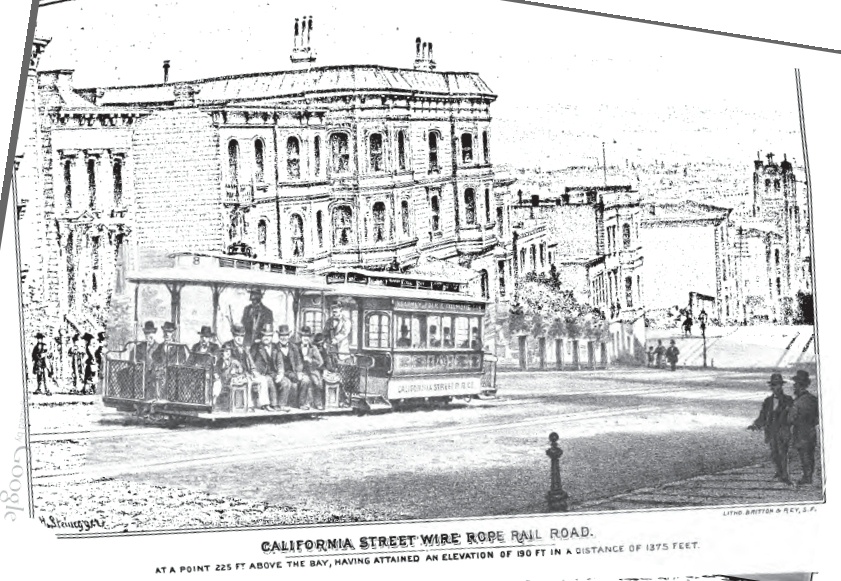
|
"California Street Wire Rope Rail Road. At a point 225 ft. above the bay, having attained an elevation of 190 ft. in a distance of 1875 feet." The original scan was a little crooked. |
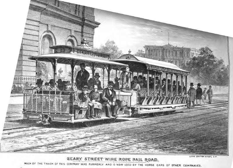
|
"Geary Street Wire Rope Rail Road. Much of the track of this company was formerly and is now used by the horse cars of other companies." The original scan was a little crooked. |

|
Profiles of street grades of three companies. Fig 7 - Clay Street, Fig. 8 -- California Street, Fig. 9 -- Geary Street. |

|
Profiles of street grades of two companies. Fig 10 - Sutter Street, Fig. 11 -- Presidio and Ferries. |

|
Clay Street Hill "Passenger car and dummy, with gripping attachment, wire rope and side section of tube." |

|
Clay Street Hill "Section through dummy & road bed showing cable and gripping attachment. Fig 2." |

|
Clay Street Hill "Isometrical view of road bed with grip and part of shank. Fig 3." |

|
Clay Street Hill "Fig. 4 -- Perspective view of grip. Fig. 5 -- Skeleton view of grip. Fig. 6 -- Cross section of tube, pulleys, etc. Clay St. Hill R. R." |

|
"Plan of engine room of Clay St. Hill R. R." |

|
"Elevation of engine house of Clay St. Hill R. R." |
Go to top of page.