Sydney's New Tramway.
THE OCEAN-STREET CABLE LINE.
THE POWER HOUSE,
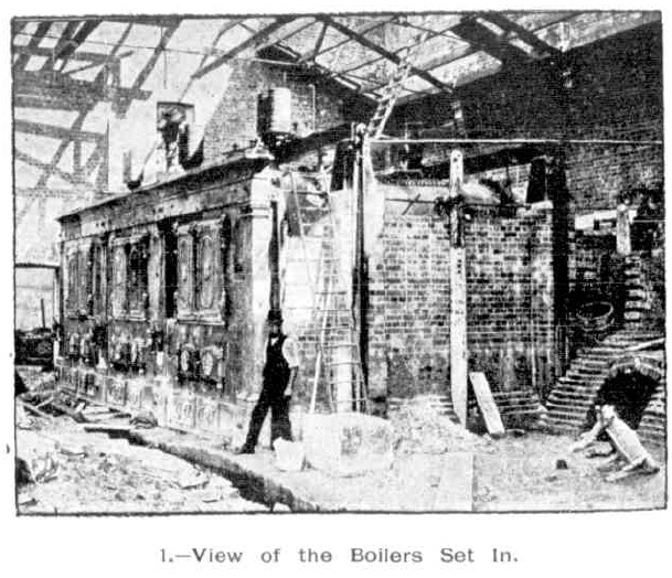
THE ENGINES AND BOILERS.
|
This article, from Australian Town and Country Journal, August 11 1894, describes a cable railway powerhouse New South Wales Government Tramways in Sydney.
The steam trams are familiar enough to all who have ever visited Sydney. They reach into all the suburbs and converge into Elizabeth street. One area has however never been touched, and that is the harbor side from Woolloomooloo to Rushcutter's Bay. It was thought that a cable service would be best for this line, and accordingly the line was laid down and the powver house built. This week we give illustrations of the machinery which will operate the cables. It is said that the total cost of the new line will not be far short of Ł140,000. Included in this estimate are Ł24,000 for machinery, Ł20,000 for the buildings, and Ł38,000 for constructing tho line. The route of the tram line is from the foot of King-street, along that street in an easterly direction as far as St. James's chambers, thence passing west of St. Mary's Cathedral down Boomerang street and into William-street, following this street up to its intersection with Victoria-street. Up to this point the tram way has consisted of a double line, one portion of which goes thence via Upper William-street South, and the other via Bayswater-road. The two lines are again brought into association immediately below the Waratah Hotel, and thence the New South Head-road is followed as far as the Edgecliffe Post Office. The gauge is 4ft 8 1/2in, corresponding with the ordinary tram line. The cable will travel along a tubular chamber having a concrete foundation. In the construction of this chamber cast-iron frames have been used. The frames are 3ft 6in apart. Bolted on to them are slot beams, bent over the cable in such a way as to leave a slot 7/8in wide, through which the grip of the dummy will pass. It is said that persons owning buggies with wheels which are light in character will find it necessary to be careful to avoid the slot already referred to. The tube frames are 19in in depth and 81/2in in width (inner measurement), it having been found as the result of experience that a depth of 19in will give quite as satisfactory results as a depth of 39in which is said to obtain in Melbourne. The permanent way is bolted to the slot beams on either side by adjustable tie-rods. The rails, which are of steel, were imported, weigh 86lb to the yard, and are each 30ft in length. The slot beams weigh 62 1/2lb to the yard, and are 21ft in length. The cable will pass over a series of sheaves 12in in diameter, and its adjustment will also be controlled by five tangent wheels, fitted in large pits, which have been constructed near the junction of Glenmore-road with the South Head-road, at the top of Upper William-street South, at the top of William-street, at the top of Boomerang-street, and also near the northern end of St. Mary's Cathedral. The tangent wheels are each 9in in diameter, and they have all been erected in chambers under the roadway, which are 14ft wide by 13ft. To assist in the adjustment of the cable, sets of depression gear have also been fitted in William-street (two sets) and in King-street. To ensure the drainage of the line, 6in earthware pipes have been laid in the concrete under the tubular chamber in which the cable runs, and at intervals along the line there are covered man holes, which serve the double purpose of giving access to tho sheaves and enabling the soil that washes through the slot to be lifted out. The route traversed, although the best obtainable in the circumstances, is far from being a good one from an engineering standpoint, the contour of the roadway presenting many irregularities, added to which were the difficulties occasioned by the curves encountered. The steepest grade is said to be 1 in 8 3/4, and the curves range from 660ft down to 72ft radius. The cables, of which there are two to be used (four have been procured), will be carried -- one eastward making a circuit, and the other westward of the engine-power house making a second circuit, the latter cable running to and from the King-street terminus -- a distance of one and three-quarter mile -- will be 20,550ft in length, and will carry the cars at the rate of eight miles an hour. The eastern cable will be 7450ft in length, and, there being much less vehicular traffic to be encountered on the route traversed by it than in the case of the longer cable, it will travel at the rate of nine miles an hour. At the top of William-street a shunting loop will be in operation, so as to enable such of the cars which may have come from the city as may be desired to be there sent on the return journey, instead of having to travel to the engine-power house before the return journey is commenced.
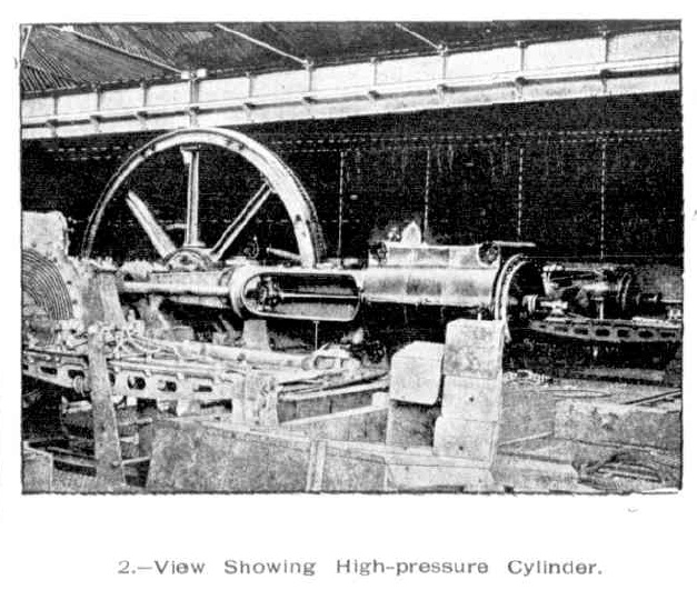
The chimney of the power house, of which we give an illustration, is said to be the highest one in Australia. The chimney rises to a height of 180ft, At the base it is 16ft square, and at the top it is 10ft across. The column is finished off with an ornamental cap built of radiating facing bricks. The main flue is 6ft in diameter, and it is thought that the chimney having been constructed on the principle of a chimney within a chimney the outer portion will be preserved from the fractures which might otherwise arise from the high temperature which is likely to prevail. The power house and carhouse are constructed of brick, resting on freestone foundations, and have a decidedly substantial appearance. The buildings are in the Romanesque style of architecture, the walls being built of double-pressed facing bricks, and the facade being set off with terra-cotta enrichments. But the feature of the structures is a clock tower, which rises to a height of 70ft. The engine house, with its complementary boiler shed, has a frontage of 100ft and a depth of 200ft. The carhouse is west of the engine-house, encloses 21,000 square feet of floor space, and was designed to house 70 cars. It will have fitted midway in it a traverser so situated as to facilitate the transfer of the cars from any one line to any other that may be desired. Opposite to the carhouse will be a double shunt connected with each of the main lines.
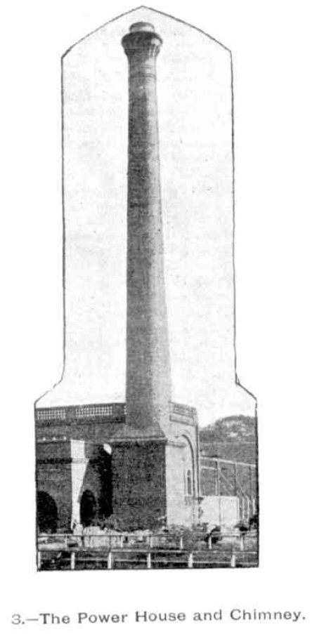
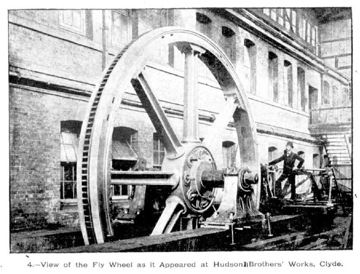
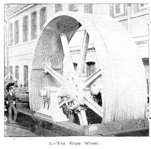
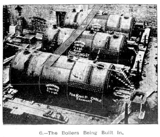
The machinery embraces two sets of horizontal compound Corliss surface condensing engines, each capable of indicating 1000 horse-power. The high-pressure cylinder is in each case 24in in diameter, and the low-pressure cylinder 45in in diameter. The stroke of the engine is 5ft 6in. The engines work with a boiler pressure up to 120lb to the square inch, and the running speed is 56 revolutions per minute. Each set of engines has a condenser working off the tail rod of tho low-pressure cylinder by means of a bell crank. There are two sets of duplex circulating pumps, each capable of delivering 30,000gal of water per hour, the water being pumped through a suction pipe 1000ft in length carried in Rushcutters Bay. Two direct-acting duplex feed pumps are also provided, each with 2000gal of water per hour. All the steam pipes are made of solid drawn copper. The main crank shaft is in three sections, and measures 55ft 9in between the centres of the outer cranks, The main shaft (which was imported) is 16in in diameter, and was made of hydraulic forged steel. The flywheels of the engines are each 22ft in diameter, and 25 tons in weight. The engines have been made to reverse. The casting for the low-pressure cylinder weighed in the rough ll tons. The driving gear consists of two rope wheels 7ft in diameter, which are mounted on a shaft in line with the main engine shafts, and can be connected at will with either set of engines. These wheels drive on to two other rope wheels 21ft in diameter, which are mounted on the same shafts as the drums for driving the cables. Each of the rope wheels is provided with 18 groves (grooves - JT)
Go to top of page. |
Home/
What/
How/
Where & When/
Who/
Why
Chronology/
Miscellany/
Links/
Map/
Bibliography
Copyright 2011 by Joe Thompson. All rights reserved.
Last updated 01-October-2011